In during time in your life, maybe you thought about this question in your mind that why a bicycle falls to the ground in off state without holder column (in stop stage); but the moving bike can keep its balance? Gyroscope physics is one of the hardest concepts in physics that requires a lot of care and attention to understand it. For the first time, the French physicist Leon Foucault (in 1852) used this tool to illustrate the motion of the earth. When the gyroscope begins to rotate, the first question that comes to mind is why, despite gravity, does not fall on the ground. In this study, we can see that the concept is well understood without the need for the use of complex mathematics. Here, the motion of the gyroscope is shown.
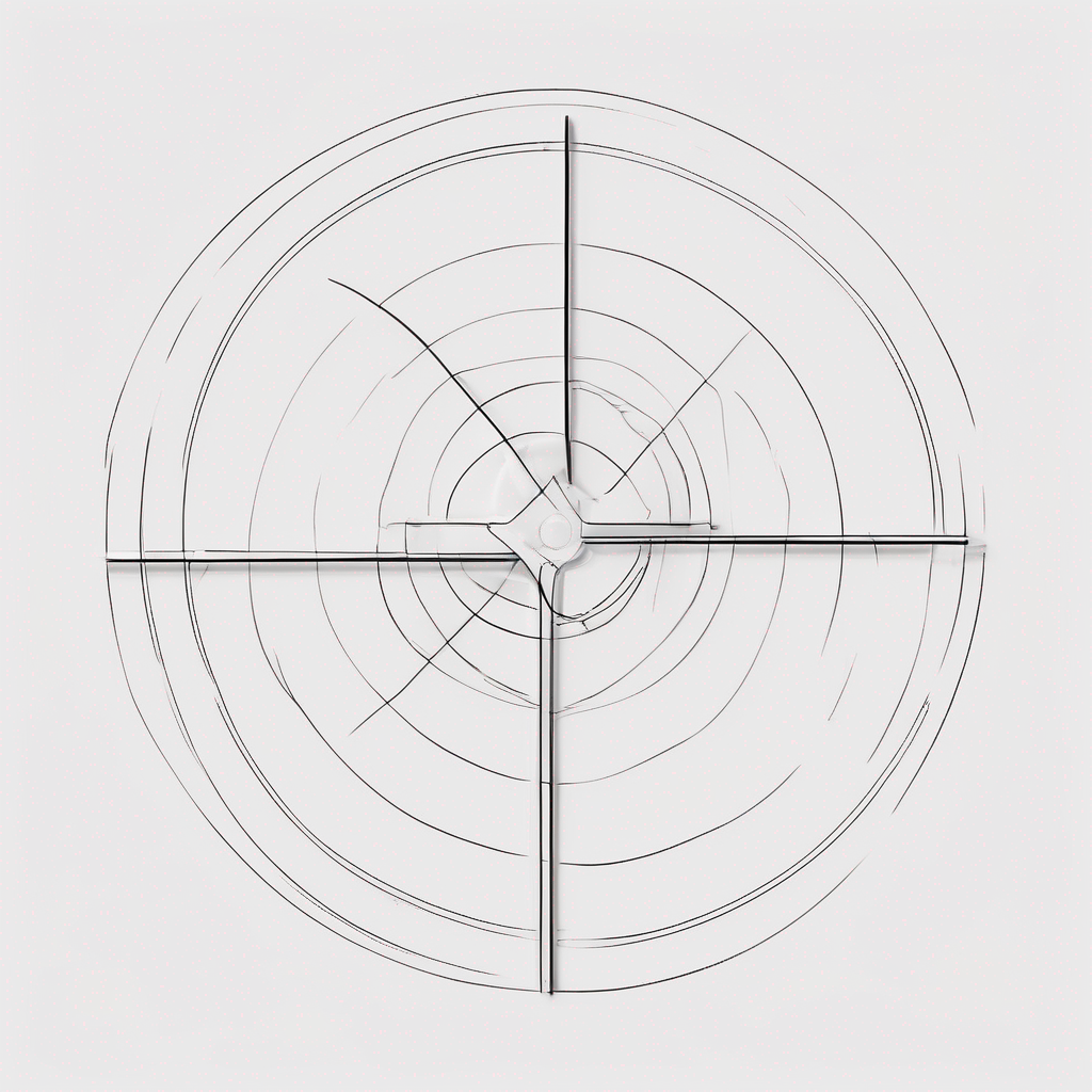
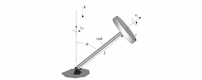
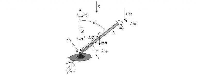
The schematic and diagram of a gyroscope can be plotted as follows. In this figure, you see, the constant angular velocity of the disc is shown with ωs and in radians per second. ωp is represents the precession velocity and is measured with radians per second. The length of the rod is represented by L and the radius of the disk with r. The angle θ represents the angle between the bar and the line perpendicular to the ground and has a constant value. When the disk rotates at an angular velocity ωs, the forward the gyroscope precession velocity around the hinge on the ground is ωp (the angle θ remains constant in this motion). Now we want to answer the question that was raised at the beginning of the research.
According to the graph and due to the compound rotation and with ωs and ωp angular velocities, the torque is entered into the rotary disk. This torque is proportional with the external multiplication of two vectors ωs × ωp. We use the law of the right hand to determine the direction of this torque. As a result, the torque is logged in counterclockwise direction. On the other hand, the gravity force causes to move in the clockwise direction to the disk. The opposite of these two torques, that is opposite, prevents the gyroscope from falling. Now we write the motion equations for a gyroscope.
Mathematical analysis of gyroscopes motion
Here, we draw the XYZ coordinate axes such below graph for a gyroscope. Axes of the coordinates are fixed.
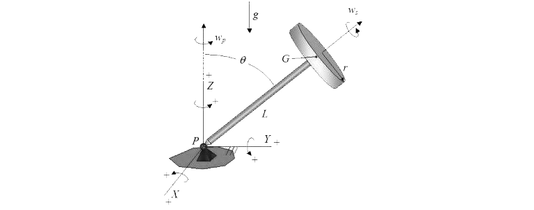
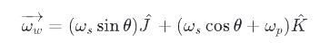
In the diagram above, g is the gravitational acceleration symbol of the earth. G is represents of the disk mass center. The pillow location is represented with P. The orgin of the XYZ coordinates is P point. The vectors I, J, and K are unit vectors, and respectively, showing the X, Y, and Z axis. In this case, the angular velocity of the disk relative to the ground is obtained as follows
By derivation from the above relation to time, the disk angular acceleration is calculated as follows.
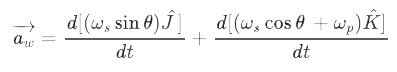
As we have already mentioned, ωs is constant. As a result, its derivative is zero, and to calculate the above relation, only the derivatives of the unit vectors must be derived. In this way, the acceleration relation is simplified as follows.

The angular velocity of the rod is calculated by the following equation.

Since the angular velocity of the rod is constant and does not change its direction, the angular acceleration will be zero.
Disk analysis
In this part, we want to analyze the forces and acceleration that enter to the disk. The disk free body diagram is shown in the figure below. In this form, we separate the rod from the disk. Note that the xyz local coordinate system is fixed on the disk and moves along with it. The origin of this coordinate system is G point. Note that the X axis is parallel to the X axis.
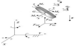
Here (above graph), we show torque at point of G and along the x-axis with Mx. The torques of My and Mz are also defined in a similar way. Also, the FGX represents of the force at point G and is same direction with the X axis. The FGY and FGZ forces are same direction with Y and Z axes, respectively. We write Newton’s 2th law for disk.

In the above relations, the disk mass is shown with mw. The aGX shows the acceleration at point G and at same direction X. The aGY and aGZ accelerations are also identical in Y and Z directions, respectively. Since the point G moves in a circular and constant-velocity horizontal direction, the tangential acceleration is zero.

Consequently, we only consider the second and third relations. Moving the G point on the circular path creates center oriented acceleration. This center oriented acceleration is toward the center of the rotation. Therefore, the acceleration and force relations are written as follows.

Since we see that the point G moves with a constant velocity on a horizontal circle, the acceleration in Z is zero.

Now, we use the Euler motion equations in the x direction for a rigid body. These equations are zero in two other directions. As we know, xyz coordinate systems are in the main directions of disk inertia.

Note that by looking at the shape, the FGX, FGY, and FGZ forces around the G point does not give any acceleration. Because all three forces pass through point G and the length of the torque texture is zero. In the above equation, IGx, IGy, and IGz respectively shown inertia moment at around the point G in the directions y, x, and z. The amount of the disk inertia moments due to symmetry is calculated as follows.

Consequently, the Euler equation is obtained in x direction.

The rod analysis
In this part, we will check the torques entered into the rod around P. The rod free body diagram are plotted as follows. The xyz coordinate system is designed to move with the rod. The coordinate origin of this rod is at P point. Also, the axes of this machine are in line with the main directions of inertia rod.
Here in this equation the point P is considered as a non-friction hinge. As a result, there will not be any torque on the rod. To calculate the torque at point P, we write the Euler motion equation in x direction

(The velocity and angle acceleration) of rod in xyz can be written as follows.

In the above equation, IPx, IPy and IPz, respectively, show the inertia moments the rods around point P in the directions y, x, and z. The inertia moments of the rod are calculated as follows. In the relationships below, mr represents the mass of the rod.

As a result, the Euler equation in the x direction is written as follows.

By integrating relationships 1 through 4, we get the following result.

Now can solve this relationship for each of the parameters ωp, θ, and ωs, and obtain each of them in terms of two other parameters.