Abstract
At first glance, we can say that there are various flying conditions for quadcopters governing. These flying conditions can include altitude, conditions and angles of rotation and safe landing spot and also avoidance of collisions with obstacles and so on. These includes reconfiguring and optimizing energy consumption, estimating flying conditions, and so on. The most important arguments in quadcopters are error control and quadcopters tolerability error in the event of error. One of these arguments that is highly regarded by researchers is that the error control is due to the failure of one or more propellants.
Introduction
Multicopters have taken into consideration in recent years. Due to its simplicity and function, they are used in a wide range of applications, such as cultivation and monitoring of infrastructure and whale monitoring. Here, we look at a particular type of Multicopters with four engines known as quadcopters. However it is necessary to mention that researchers have studied this particular type widely and there are extensive articles on design, modeling and design of the path, and so on. This type of devices are susceptible to various types of failures in their systems, such as incomplete or complete loss of engine or propeller, collision with obstacles or collision with other vehicles and power outage. The fault tolerance control in the quadcopters can be helpful in case of partial or complete failure of the actuator. One of the using strategies, is defining an axis that with respect to the body of device will fixed and the vehicle rotates freely on this axis. By rotating this axis and changing the total production amount of thrust, the vehicle’s position will be controllable. One of the most obvious issues during quadcopters operation is propeller or motor failure, and the evolving scenario is handling fault tolerant in quadcopters during flight.
Issue
We are here overviewing this issue that quadcopters, even in a model that has a tilt-rotor, can also complete the flight mission with least difficulty in flight performance. Of course, we just consider the status of propellers (rotors) and as a result of wide variety of other topics, here it is not necessary to consider these issues. Often in a quadcopters, a set of two diagonally opposite propellers rotate with clockwise spin and the other two propellers spin in counter-clockwise direction. Tilt-rotor quadcopters also can use different rotation configuration.
We assume that the direction of rotation of the adjacent propeller of a propeller is in the same direction as shown in Fig. 3. The main advantage of the use of rotational configuration is that the quadcopters can be transformed into T-copter by structural deformation of one failure propeller. We can also control the operation of the propeller and movement of quadcopters by using equations of motion. Of course, it is worth mentioning here that in the motion of quadcopters, air resistance, type and substance and weight of propeller engine is affected, too and here the condition of unstable air and very detailed engine details is not considered.
Equations of motion
One of the most fundamental parts of the vertical flight system (here, we consider quadcopter) is the ability to stay in the air, which distinguishes it from other aircraft systems, and for quadcopter’s movement, some equations is ruling. First, the translational and rotational dynamics, followed by some simplifications for the sake of tractability. To write dynamic equations, one cannot often consider all the parameters involved in a phenomenon, because natural systems, especially in this case, fight system is complicated and various factors is influencing dynamics and motion, for this reason, we don’t consider some parameters to simplify the work, and on the other hand, we must consider conditions in a real situation.Here we use the g symbol to represent the three-dimensional vectors, while we use the m symbol for scalars. The short hand notation \(W^B=(p,q,r)\) will be used to denote the elements p, q, and r of the vector \(W^B\).
.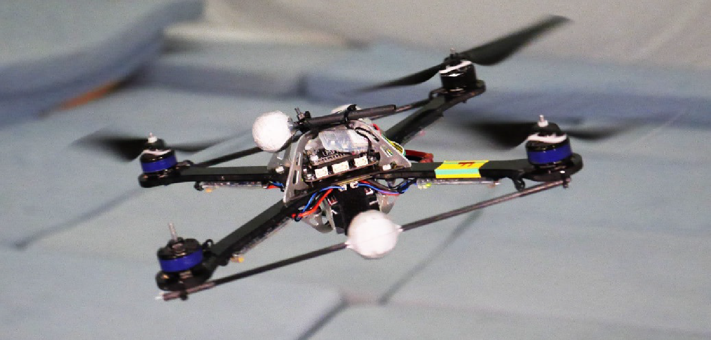
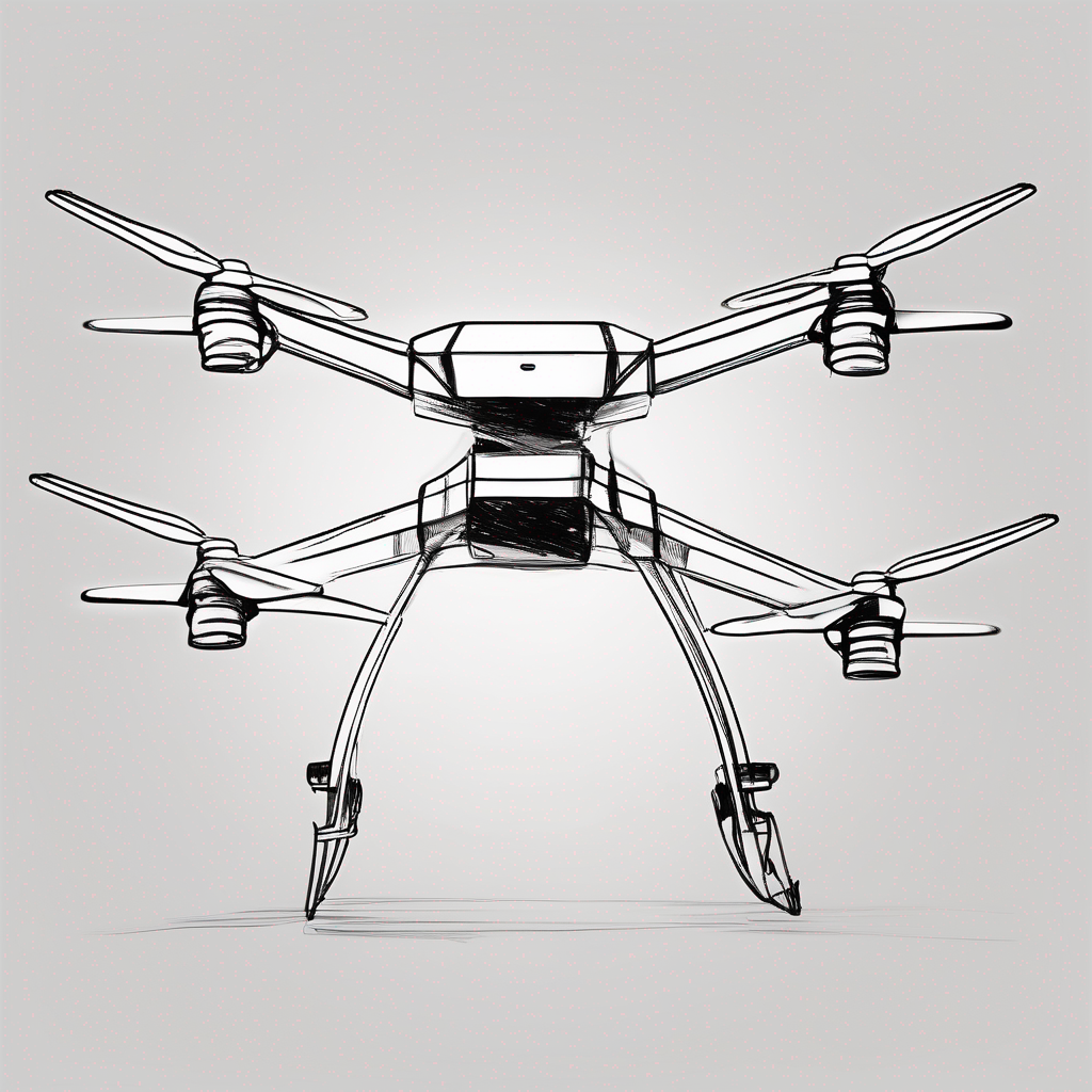
Fig. 1. A quadcopter in controlled flight despite having lost one complete propeller.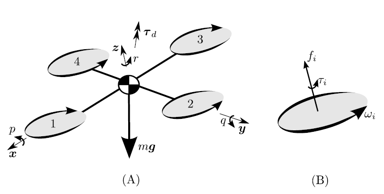
Fig. 2. (A) A dynamic model of a quadcopter with four propellers arranged symmetrically about the vehicle center of mass, showing a body fixed reference frame consisting of the directions x, y and z. Propellers 1 and 3 rotate in the opposite sense of propellers and 2 and 4. A drag torque Td acts to oppose the vehicle’s angular velocity \(W^B\). expressed in the body fixed frame as \(W^B\).=(p, q, r) . The vehicle has a weight force mg. (B) shows a detail of a propeller \(i\) rotating at angular velocity wi with respect to the body. Each propeller produces a thrust force \(fi<0\) and torque \(Ti<0\), both in the direction of the propeller’s axis of rotation. As drawn in (B), \(Wi>0\). and \(Ti<0\) .
Dynamic
In Fig. 2 we show one quadcopter, with four propellers, and a total mass m. Five forces act on the vehicle: the weight mg, and the four propeller forces of magnitude \(F_i\) which act in the body-fixed direction z=(0, 0, 1) as defined in the figure. Additionally, five torques act on the vehicle: one for each propeller (captured by the scalar \(T_i\)) and a drag torque \(T_d\).
The propeller torques oppose the propeller’s rotation, and the vehicle drag torque \(T_d\) opposes the vehicle’s angular velocity. Expressed in a body fixed reference frame, the vehicle’s angular velocity is \(W^B\)=(p, q, r) . The rotation of the body fixed frame with respect to some inertial frame is described by the rotation matrix R.
The position of the quadcopter’s center of mass, expressed in the inertial frame, is denoted \(d= ( d1, d2, d3)\).
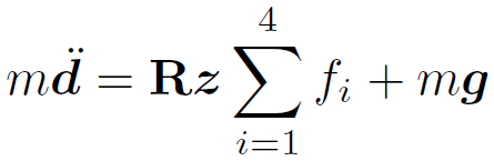
Then, the quadcopter’s translational dynamics are:
In the following, we discuss about a dynamic model of the air system, which includes the equation of motions for two cases governing the flight. The first case where all propeller motors are functional. The second case includes the dynamics after one or many propeller failures, basically the quadcopter’s aerial system is reconfigured.
Here, we consider a modified spin configuration for propellers, as shown in Fig. 3. The sine and cosine angle terms are shown in Fig. 3.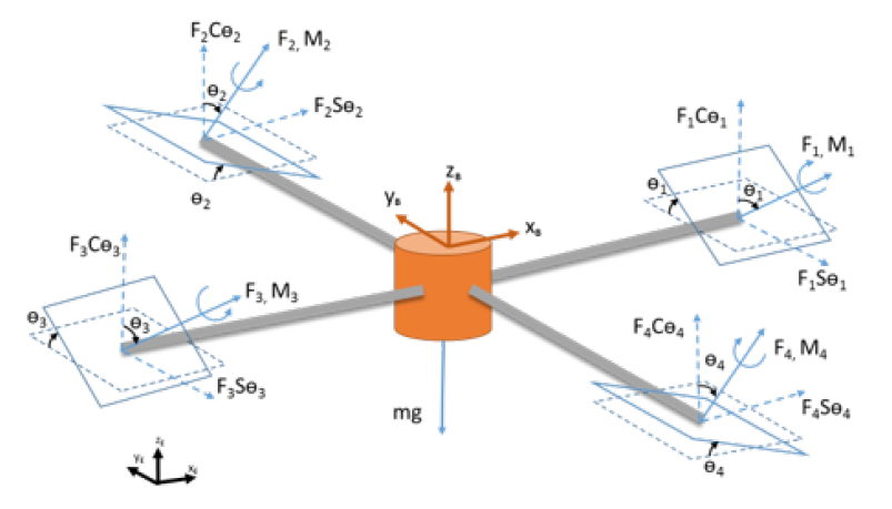
Fig. 3. Tilt rotor quadcopter free body diagram (all propellers are in use)
A: UAV dynamics for when all propellers are in use
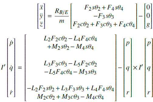
All motions of the device are considered with respect to the world frame. Similarly, the body fixed frame is connected to the center of gravity of the device and moves along with quadcopter. The direction of forces and moments due to rotational and tilt motion of the rotors are shown in Fig. 3 and Fig. 4. The planes shown with dashed lines are the original planes of the rotation with zero tilt angles whereas the planes shown with the rigid lines are the planes after exercising tilt. The propeller forces are first transformed from propeller frame of references to body frame by using Euler angle transformation defined by successive rotations about x, y, z axis by , and angles which represent yaw, pitch and roll angles respectively. The transformation matrix \((R_B |_E)\) is a directional cosine matrix relating body frame parameters to the world frame. Referring to the free body diagram of tilt rotor quadcopter, the equation of translational motion in world frame is shown as follows:
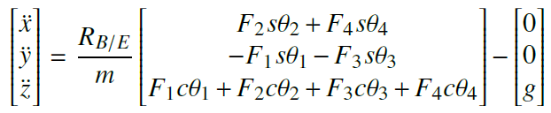
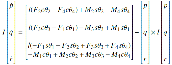
\( \theta _i , \forall i \in {1, 2, 3, 4 } \) are the rotor tilt angles, m is the total mass of quadcopter, g is the acceleration due to gravit \( \ddot y, \ddot x, \ddot y\) and \( \ddot z\) are the linear accelerations in world frame, \(F_i , \forall i \in {1, 2, 3, 4 }\) are the forces produced by the four rotors. The thrust force produced by the propeller is directly proportional to the square of angular speed of the propeller. Similarly, the equations for rotational motion of the tilt rotor quadcopter are written by calculating the effective torque in the body frame of the quadcopter is shown as follows:
We must take into account that in the case of a situation where one and three propellers are disabled and stopped, the resulting forces and motions on the device will not be zero, to the point where there is no static equilibrium for the center of mass of the device.
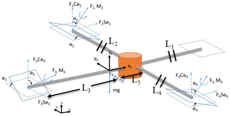
Fig. 4. System after structural reconfiguration (one of the propellers is failed or stopped)
B: UAV dynamics when a propeller is failed or stopped
Here, the dynamics of the structure of quadcopter upon failure of a propeller is introduced. That means, without interrupting the whole subject, as shown in Fig. 4, the engine 1 supposed to be stopped. The arm opposite to the failed motor is longer as compared to other arms in order to yield the required quadcopter configuration. The center gravity of the system shifts towards negative \(x_B\)-axis and the moments of inertia matrix of the system also changes to l’. The force and moment equations governing the motion of the quadcopter are shown below:
The force and moment terms associated with the first rotor are no longer part of the system due to motor failure. Here, l’ is the new moment of inertia matrix about the body axes. \(L_i\), \( \forall i \in {1, 2, …5 } \) are the UAV arm lengths as shown in Fig. 4. The length of longer arm of quadcopter is equal to the sum of \( L_3\) and \(L_5\). It is generally equal to \( \sqrt 3 \) times \( L_1\) to yield required quadcopter system.
If the resulting forces and moments on the object are zero, the object is said to be in equilibrium. Here, the force equations of motion show residual acceleration terms in x, y direction. Similarly, the moment equations also show similar characteristics for pitching motion.
Conclusion
Various influential factors, such as dynamic factors and gravity effects, etc., have roles in the stability of quadcopter. However, there are various other areas, such as dealing with obstacles and landing sites, and so on can be considered, because of extensive discussions, we cannot bring them here. The mentioned equations are general and may not be comfortable for any kind of quadcopter with specific shape and size, and this can be matter for future work to examine that issues.
References
[1] Hedayatpour, M., Mehrandezh, M. and Janabi-Sharifi, F. (2018). Path Planning and Controlled Crash Landing of a Quadcopter in case of a Rotor Failure.
[2] Kumar, R., Sridhar, S., Cazaurang, F., Cohen, K. and Kumar, M. (2018). Reconfigurable Fault-Tolerant Tilt-Rotor Quadcopter System. Volume 3: Modeling and Validation; Multi-Agent and Networked Systems; Path Planning and Motion Control; Tracking Control Systems; Unmanned Aerial Vehicles (UAVs) and Application; Unmanned Ground and Aerial Vehicles; Vibration in Mechanical Systems; Vibrations and Control of Systems; Vibrations: Modeling, Analysis, and Control.
[3] W. Mueller, M. and D’ Andrea, R. (2014). Stability and control of a quadrocopter despite the complete loss of one, two, or three propellers. In: IEEE International Conference on Robotics & Automation (ICRA). Hong Kong: IEEE International Conference on Robotics & Automation (ICRA).